PCBA functional testing refers to testing the electrical continuity of a PCBA circuit board with mounted electronic components by simulating its operation under actual usage conditions. Based on input/output values, this ensures the board functions correctly according to a pre-defined plan. PCBA functional testing helps avoid manufacturing and quality issues, reducing unnecessary repair costs. It also ensures that products delivered to customers are intact, improving customer satisfaction. Furthermore, PCBA functional testing is a crucial means of optimizing PCB design, identifying and eliminating potential problems and defects during the testing process. This helps improve and optimize the circuit board design, increasing its reliability and stability, thereby significantly reducing the risk of failure and malfunction.
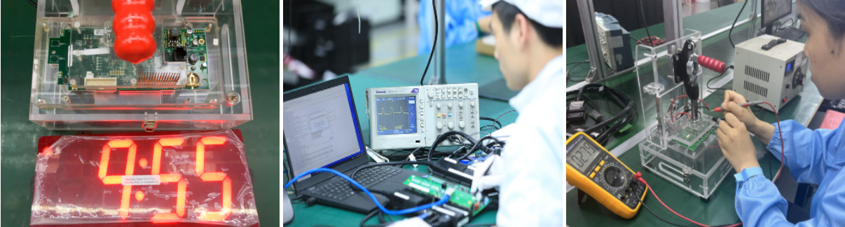
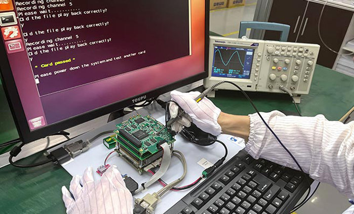
For large-scale PCBA functional testing, corresponding test fixtures are typically provided to facilitate efficient testing. The principle of the test fixture is to connect test probes to test points on the PCB board. When power is applied, key data such as voltage and current in the circuit are acquired and displayed on the test fixture's screen, achieving rapid detection. When customers design their PCB boards, engineers need to consider their testing plans, reserve PCB test points, and provide us with professional test documentation or test plans.
Conformal Coating: For electronic devices operating in harsh environments such as high humidity, high salt, dust, and vibration, PCBAs are susceptible to system failures due to salt spray, moisture, and mold. Juyuan Union can provide specialized conformal coating services.
Example: A Customer's PCBA Testing Solution
Testing Steps
1. Turn on the 5V and 12V power supplies.
1.1) On the test fixture board:
1.2) Confirm that the green indicator lights DS1 and DS2 are lit.
1.3) Confirm that the red LED DS3 is lit.
1.4) Flip the RESET switch up first, then down.
2. On the DUT board:
2.1) Confirm that the green LEDs DS1 and DS3 are lit.
2.2) Other LEDs should not be lit.
2.3) If any red LED lights up, check that jumpers P4 and P5 are connected. On the test board, toggle the RESET switch upwards and then downwards.
Measure the power supply voltage of the DUT.
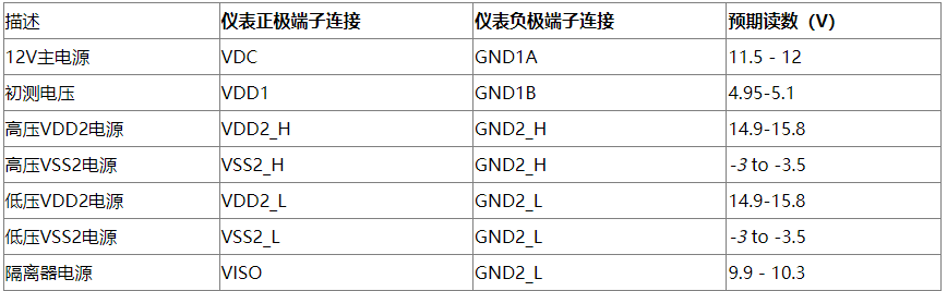
In the test fixture board, connect the meters to HS-GATE (+ terminal) and HS-SOURCE-LS-DRAIN (- terminal) �C two meters can be used in combination with D.
A. On the DUT board, place a jumper in P5.
B. On the test board, toggle the RESET switch upwards, then downwards.
C. Move the IN 1 switch to the UP position.
D. The measured value is between -3.5V and -3V.
E. Move the IN 1 switch to the DOWN position.
F. The measured value is between +14.5V and +15.8V.
G. On the DUT board, remove the jumper in P5.
PCBA functional testing is performed to ensure the electrical performance and functional stability of the product. During production, reliable PCBA functional testing can detect circuit board defects and faults early, thereby improving product quality and reliability. Meanwhile, PCBA functional testing ensures product stability, thereby guaranteeing subsequent customer satisfaction and reputation.